Light Spheres and 2125 Resistors
 My first attempt at doing some light spheres was not particularly successful – the photos were boring and the light spheres were a bit wonky.
Part of the reason for this was shoddy photography and part of the reason was using a torch on an end of a piece of string was perhaps not the best way to achieve the effect I was looking for.
I decided to make something that would be more appropriate and based it on something I saw on flickr (I’ve lost the link, will try to find it). Here are the results:
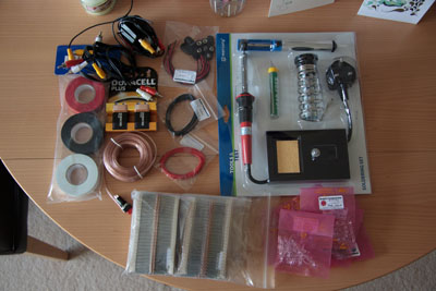
So how did I produce these? First thing was to get all the bits and bobs I needed:
- Soldering Iron, Stand and Solder
- Assorted bright LED’s
- SPST Push-to-Make switch
- PP3 Battery clips
- Resistors (2125 to be exact)
- Lots of electrical tape
- Lots of speaker cable
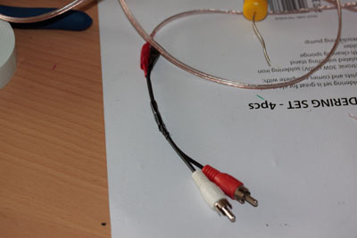
- Component cable and old SCART->Component connector
Most of the items I got off of ebay – I ended up buying the entire E12 series of resistors (20 or 30 of each value) for a tenner instead of 60p per resistor from Maplin. The Component cables and SCART adaptor I had lying around from an old Xbox.
General method:
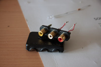
- Dismante SCART -> Component connector. Remove scart plug and join the red wire to the white wire for each audio channel together. Snip off the video cable.
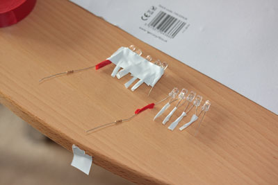
- Solder the LED’s together into a 3 strips of 5 – make sure you use the correct value resistor at the start of each strip and make sure you solder the LED’s together anode to cathode. I used this to generate the LED array for me.
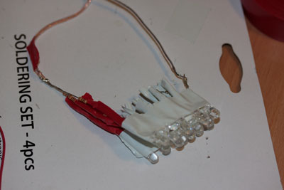
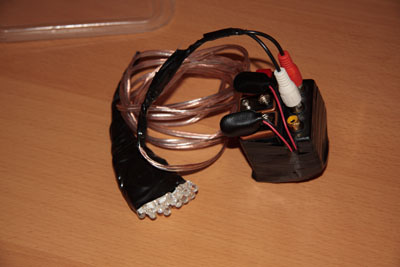
- Insulate the strips in the array and bind together. Solder to a good length of speaker cable, one wire in the speaker cable for positive, one for negative
- Take the video wire out of the component cable (Yellow cable in the triplet of Red, White and Yellow)
- Strip the red component cable so you can see the live and ground wires inside. Join these together and then attach this to the positive (anode) end of the speaker cable attached to the LED array
- Repeat with the whire component cable and solder to the negative (cathode) end.
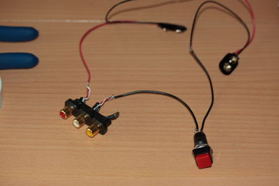
- Wire in two PP3 connectors in series to a push to make switch and solder the positive end to the wires that made up the red component socket in the SCART > Component connector stripped in step 1
- I mounted the connectors to a small box, with the connector taped to the side and bound together tightly.
- Add some 9v PP3 batteries and press the button!